SVF is the native format for the Autodesk Viewer. As well as the standalone web app, the viewer is embedded in other Autodesk web apps like Construction Cloud, desktop products with components that use web technology like Fusion, and available as an SDK for third parties to integrate into their web apps.
History
SVF is a format designed by committee. It was born when Autodesk made another of its repeated attempts to rationalize the number of different viewers in the company.
The focus this time was on web viewers. It was a couple of years after Autodesk’s pivot to the cloud. Many of the early cloud applications were essentially desktop products repurposed as frontend clients for some cloud hosted features. Product Management were feeling the pressure from startup competitors that boasted of their web native, zero install clients.
There were three contenders for the crown. The official champion was a viewer based on the acquisition of the Wild Pockets game design platform. Their viewer had a couple of significant challenges. First, it had been build with a games mindset which made it hard to adapt to viewing large design files. Second, it was written in C++ and used tools like emscripten to compile to JavaScript. Performance and memory usage was a black box, making it hard to scale to larger models.
Next into the ring was Navisworks. Navisworks provided the “web” viewer for BIM 360 Glue. The Navisworks viewer was the core of the Navisworks product, compiled as a browser plugin. At the time, all the major browsers supported native code plugins, either as an ActiveX control for Internet Explorer, or a Netscape plugin for Chrome and Firefox.
The Navisworks viewer handled large models well, but had other problems. Navisworks was a Windows only product, so the Navisworks viewer browser plugin was only available for Windows. The plugin needed to be installed on each end user’s machine and browsers were making the process increasingly complex and temperamental for security reasons. The writing was on the wall for native code plugins and most browsers dropped support when HTML5 adoption became widespread.
The third contender was the InfraWorks team. InfraWorks was another desktop application. However, the team had taken the radical approach of building a JavaScript web viewer from scratch, rather than trying to reuse their existing desktop implementation. At the time, it seemed like heresy. Throw away your mature, battle tested code base, and try to reproduce the functionality in JavaScript?
And yet, the viewer worked, for big models too. It only supported InfraWorks models, but it clearly had a lot of promise. It was written in JavaScript, so the team were able to optimize directly for performance and memory usage in the JavaScript runtime environment.
The Committee
Key members from each team formed a committee to decide the path forward. I represented Navisworks. We all felt that the emscripten like approaches were a dead end. The tooling wasn’t mature enough and we had no idea when, if ever, it would be viable. We would use the InfraWorks JavaScript viewer as a starting point. However, we needed a more general file format.
The Navisworks format was the obvious choice. It was a neutral file format, with existing converters from every significant CAD file format. However, porting the existing parsing code to JavaScript seemed like a non-starter to me. There was no spec and the code had all the warts you would expect from twenty years of evolution while maintaining backwards compatibility.
There was also the problem that Navisworks was an all-in-one format. That might seem like it should be an advantage, but it didn’t fit the way browsers worked. To get good performance from a web viewer for large models, you need to cache the model locally. As well as helping speed things up when you reload the same model, it’s critical if you need to page parts of the model in and out of memory. At the time, JavaScript had very limited access to local storage. The only practical way of caching large amounts of data locally was to let the browser do it.
The Navisworks format is designed so that you can load parts of the model on demand. You can do the same thing from JavaScript in a browser, by making range GET requests for parts of a file stored on a server. The Navisworks web plugin already worked this way but implemented its own on disk caching. The problem is that the browsers would only cache complete requests. Any range request would work but would not be cached. The model needed to be broken into separate physical parts that could be retrieved using normal GET requests.
We decided that we needed a new format based on the Navisworks model representation, with all the legacy cruft removed, that could be naturally broken up into separate parts.
The Spec
The first job was to come up with a formal spec. There would be multiple teams working on reading and writing SVF in at least two different languages (C++ and JavaScript). Using “the code” as the spec wouldn’t work.
I was a co-author of the final spec. It was a pretty straight forward transliteration of the Navisworks file structure. It covered the model representation, geometry and viewing related metadata. The object property representation in Navisworks had always been something of a compromise, so we reworked it significantly for SVF.
For the BIM 360 Glue backend we had implemented a system where properties were extracted from Navisworks files and stored in SQLite database files, one per model. The files were easy to manage, efficient to query and the SQLite engine is built to page data in and out of memory as needed. SQLite is widely used. Most browsers implement their local storage databases using SQLite.
We agreed to use a SQLite database as the property representation in SVF. The schema was based on an Entity-Attribute-Value triple store. Each instance is assigned an incrementing integer entity id (also known as a dbid) when the SVF is created. The same entity ids are used when serializing the model representation, thus tying everything together. The database has a table of property attributes which defines each type of property and specifies property name, units, etc. A table of values defines each unique value. Finally, an EAV table defines triples which specify that an entity E has a property attribute A with value V.
This turns out to be a surprisingly compact representation. Most models have no more than a few hundred different property attributes, regardless of size. There are many common values across all the objects in a model, so the value table is a lot smaller than you might think. Finally, the EAV table just contains triples of integer indexes which compress really well.
During implementation, the viewer team suggested an alternative representation. The property database representation was so compact that SQLite’s ability to page data in and out wasn’t needed. The property data is read only within the viewer so you don’t need the ability to edit it either. You could store the whole thing as a set of compressed JSON arrays. The big arrays only contain integers, so you can use a JavaScript typed array in memory. Most browsers store typed arrays outside the limited size JavaScript heap, making it practical to load all the property data into memory.
AFAIK the SVF spec has never been made public. I haven’t looked at it in years, and I suspect no one in Autodesk has either. As we’ll see later on, significant parts of what is now considered to be SVF, were added organically. The original spec helped to bootstrap the ecosystem, but after that SVF ended up being defined by what the code in the Autodesk Viewer would read.
Model Derivative Service
The final player in the SVF ecosystem is the Model Derivative service. The Model Derivative service converts design files stored in Autodesk cloud apps into SVF, as well as a variety of other formats. The service creates and manages “derivatives” of your design files. Behind the scenes is a big S3 bucket and a fleet of servers with a variety of desktop applications installed. Model derivative service looks at the type of your input design file and the desired output format, then runs the appropriate converter.
Converters are typically implemented as SVF export plugins that run within a standard desktop application. One of the SVF teams built a C++ library for reading and writing SVF files. The application teams were then responsible for using the library to write their plugin. In the early days of SVF, most conversions used Navisworks. Navisworks could read most formats, so all it took was implementing a Navisworks SVF export plugin to add Model Derivative support for twenty formats.
Model Derivative service expects all converters to output a JSON manifest in a standard format, together with a set of files described by the manifest. If you ask Model Derivative service to produce multiple different types of derivative, it merges the JSON manifests from each converter together to create a combined “bubble” of derivatives. When querying the Model Derivative service, you need to be aware that the manifest returned can contain data from other conversions that you might not be expecting.
In theory SVF is an extendable format. The initial spec was based on the Navisworks representation. As application teams started writing their own converters, they found things that Navisworks and hence SVF didn’t support. Extending SVF would mean getting the spec and C++ library updated, which would mean coordinating with multiple teams, all with different priorities. Alternatively, the application team could throw whatever extra data they wanted into their converter’s Model Derivative manifest. All they had to do then was persuade the viewer team to add support for it.
SVF Format
Enough back story, let’s get into the details of the format. I was a little worried about how much I can say, since my run in with Autodesk legal after my Navisworks file formats post.
Fortunately, the Autodesk developer advocacy team have written extensively about the SVF format, including code samples for parsing the high level structure. Many of the assets use standard file formats or are self describing, so you can work the rest out by looking at example models. Everything I want to write about is public information, if you know where to look.
I’m going to describe the format in terms of the set of files that an SVF converter writes out. If you use the developer tools in your browser, you can see the Autodesk viewer retrieving each of these files from the Model Derivative service.
I’ll start with the original SVF format, then go through what changed for SVF2.
Model Derivative Manifest
The Model Derivative manifest is structured as a tree. Each node of the tree is represented by a JSON object.
{
"guid": "aa85aad6-c480-4a35-9cbf-4cf5994a25ba",
"role": "viewable",
"type": "folder",
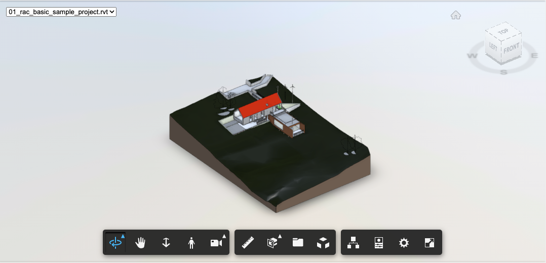
"name": "rac_basic_sample_project.rvt",
"children": []
}
Every node has a guid identifier and type. If it’s an internal node in the tree, it will have an array of children. Many nodes will have a human readable name. Some types are categorized further with a role property. Each type of node will have additional type specific properties (not shown here).
The manifest can be verbose. Complex design files can contain multiple models and views in both 2D and 3D. Each model and view is represented as a sub-tree containing thumbnails, 3D SVF, 2D DWF and F2D, viewpoints, thumbnails, additional design file specific metadata, object property databases, etc. There isn’t any fixed structure. Consumers need to iterate over the the tree looking for types and roles they’re interested in. There is sample code that will parse the manifest and download all the SVF resources.
The guid identifiers don’t have any specific meaning. They’re used when merging manifests. The Model Derivative service recurses down the tree structure of each manifest, merging nodes with the same guid.
Downloadable content is represented by nodes with the “resource” type. Resource nodes have an urn property which can be used to download the corresponding content from Model Derivative service. SVF files have the “graphics” role and a mime type of “application/autodesk-svf”.
{
    "urn": "urn:adsk.viewing:fs.file:.../output/Resource/3D View/{3D} 960621/{3D}.svf",
    "role": "graphics",
    "size": 5242199,
    "mime": "application/autodesk-svf",
    "guid": "6bfb4886-f2ee-9ccb-8db0-c5c170220c40",
    "type": "resource"
}
SVF resources usually occur as a child of a “geometry” type node that has additional metadata such as a name and viewableId. The geometry node can contain other children such as saved views.
{
    "guid": "250a6ce5-ee70-fdca-bfc9-4111f54e9baa",
    "type": "geometry",
    "role": "3d",
    "name": "{3D}",
    "viewableID": "44745acb-ebea-4fb9-a091-88d28bd746c7-000ea86d",
    "children": []
}
Multiple Versions of Design Files
Each version of a design file managed in the cloud will have its own derivatives described by a Model Derivative manifest. If you want to understand how a design file has changed over time, you will need to identify the corresponding geometry resources across multiple manifests. Remember that each design file can contain multiple sheets and models.
You might think that’s what the guid property is for. However, some converters generate new guids every time they export, so you can’t rely on guids being stable across versions. The viewableId property is an identifier that should be meaningful to the source design application. You can rely on it being stable if it’s present, but not all converters output one. The name property is the last resort. It’s usually a human editable name so may occasionally change from version to version.
The heuristic most consumers end up using is to try matching up resources on each property in turn: guid, then viewableId, then name. Stop when you find a match.
SVF container
You’ve parsed the Model Derivative manifest, identified an SVF resource and downloaded the corresponding content. What have you got? Luckily, there’s sample code that shows how to parse the top level of the SVF file.
The top level SVF container is a ZIP file. Change the extension from .svf to .zip and open it up to see what’s inside. Typically, all you’ll find is two JSON files: manifest.json and metadata.json.
Metadata.json contains properties that apply to the entire file. Things like units, world bounding box, geo-coordinates, up and north directions.
When designing the SVF format, we wanted to have the flexibility to use it as a multi-part web format or an all-in-one desktop format. Each part can be stored in the .svf ZIP file, or as a separate external file. The manifest.json file lists all the parts and tells you whether they’re embedded in the ZIP file or referenced externally.
    "assets": [
        {
            "id": "objects_attrs.json",
            "type": "Autodesk.CloudPlatform.PropertyAttributes",
            "URI": "../../objects_attrs.json.gz",
            "size": 0,
            "usize": 0
        },
        {
            "id": "CameraDefinitions.bin",
            "type": "Autodesk.CloudPlatform.PackFile",
            "typeset": "0",
            "URI": "CameraDefinitions.bin",
            "size": 140,
            "usize": 177
        },
        {
            "id": "metadata.json",
            "type": "Autodesk.CloudPlatform.ViewingMetadata",
            "URI": "embed:/metadata.json",
            "size": 491,
            "usize": 975
        },
        ...
    ]
The manifest has a top level assets property which lists all the parts of the SVF. Each asset has a URI property which tells you where the content is stored. If the URI starts with embed:, it’s stored in the ZIP, with the filename given by the rest of the URI. Otherwise, the URI is a relative path to an external resource. Most of the time, the external resource is in the same directory. However, it’s possible for the resource to be stored in a sub-directory, or as shown here, higher up in the directory hierarchy.
There are size and usize properties which tell you the compressed and uncompressed sizes of the content. In some cases, the implementers were lazy and just wrote out 0. It’s safest to ignore the stored sizes and use the actual size of whatever content you’ve downloaded.
The id property is a unique identifier within the list of assets. It’s usually just a truncated version of the URI.
Finally, there’s a type property which tells you what kind of asset you’re looking at. The type specifies the format of the content. Some types, like “Autodesk.CloudPlatform.PackFile”, are containers. An additional typeset property provides information about the types of object stored in the container.
The typeset property is the id of a typeset object from the typesets top level property.
    "typesets": [{
        "id": "0",
        "types": [{
            "class": "Autodesk.CloudPlatform.Camera",
            "type": "Autodesk.CloudPlatform.CameraDefinition",
            "version": 2
        }]
    },{
        "id": "1",
        "types": [{
            "class": "Autodesk.CloudPlatform.Light",
            "type": "Autodesk.CloudPlatform.LightDefinition",
            "version": 1
        }]
    },{
        "id": "2",
        "types": [{
            "class": "Autodesk.CloudPlatform.Geometry",
            "type": "Autodesk.CloudPlatform.OpenCTM",
            "version":  1
        }]
    },{
        "id": "3",
        "types": [{
            "class": "Autodesk.CloudPlatform.Geometry",
            "type": "Autodesk.CloudPlatform.OpenCTM",
            "version": 1
        },{
            "class": "Autodesk.CloudPlatform.Geometry",
            "type": "Autodesk.CloudPlatform.Lines",
            "version": 2
        }]
    },
    ...
    ]
Each typeset has an id, referenced by the container asset, and an array of types. Most containers store a single type of object, but some, like geometry containers, can store multiple types. The version property tells you which version of the serialization format was used for objects of that type.
Pack Files
Pack files are a generic lightweight container format, similar to a ZIP file, used for many SVF assets.
Generally, the objects stored in pack files are small. So, rather than compressing each object individually, the whole pack file is compressed. In cases where random access to individual objects is needed, multiple pack files are used with a limit on the size of each individual file.
Serialization
Serialization is far simpler for SVF than it was for Navisworks. We realized that we could serialize everything as simple arrays of objects, and reference other objects by index. Each array is a separate asset stored in a pack file. There’s no need for graph serialization.
Shared references are modelled by separating instances and definitions into separate assets.
Viewing Metadata
SVF supports a basic subset of the Navisworks metadata. Specifically, saved viewpoints (cameras in SVF), lights and selection sets (sets in SVF). The original intention was to add support for more once we understood how the viewer would be used.
Saved viewpoints are an odd case as they can be stored in both the SVF and the Model Derivative manifest. In the end, the Model Derivative manifest won out and those are the saved viewpoints you see in the viewer.
The only extension to the metadata that I can remember is adding support for saved viewpoint visibility overrides. This was done without changing the SVF format. The viewer didn’t use the sets feature in SVF. That was repurposed to store a set of entities for each viewpoint that should be hidden. The set index was then added to the saved viewpoint definition in the Model Derivative manifest. After all, it’s JSON, just throw in another property.
Model Representation
You’ve probably recognized the common theme by now. The SVF model representation is based on Navisworks.

The instances and geom refs from the spatial graph work the same way. Instances are stored in the “FragmentList” asset, geom refs in the “GeometryMetadata” asset. Each instance includes an entity id to identify the entity it’s part of.
These two assets are special in that they don’t use the pack file format. They have their own specialized container formats. Large models contain huge numbers of small instances and geom refs so we wanted to be as efficient as possible.
There’s no serialized spatial hierarchy. The viewer uses an optimized spatial hierarchy that can be built at load time from the geometry metadata. There’s also no logical scene graph. Once all the object properties were moved out to a separate database it wasn’t needed any more. The viewer can display the same selection tree using the instance tree representation. So, instead of serializing the logical scene graph and using it to build an instance tree at runtime, we just serialize the instance tree.
The viewer team later realized that the serialized instance tree wasn’t needed either. All that it’s doing is defining a parent-child relationship between entities. That could easily be modeled as an object property. The instance tree is still there in the SVF package but the viewer never loads it.
Geometry
Geometry is serialized into a set of pack files, with a new file started when the pack file size exceeds 512 KB. Each geometry pack file is identified by an integer id. You’ll see files named “0.pf”, “1.pf”, “2.pf”, etc. The geometry metadata stores the pack file id and index within the pack file for the corresponding geometry.
SVF uses OpenCTM for serialization of triangle meshes. I can’t find a public description for what was used for the other geometry types like line and point sets.
When an SVF model is loaded into the viewer, all the model representation assets apart from the geometry are loaded up front. Geometry pack files are downloaded on demand as the geometry is needed for rendering. The viewer relies on the pack files being cached by the browser for good performance.
Materials
Materials are stored in the “ProteinMaterials” asset as compressed JSON. Autodesk had (multiple) long running initiatives to define a common material model across all applications. Protein was the code name for that year’s common material model. Protein already had support for serialization to JSON. Most models use a limited number of materials, so we just used the protein serialization as is.
Object Properties
I’ve already mentioned that object properties use an Entity-Attribute-Value triple store representation. The standard pipeline for writing SVF adds all the properties to a SQLite database, which you can download from Model Derivative service if you want to. At the end of conversion, the database is converted into a set of five compressed JSON array assets.
The arrays are written with a particular formatting that, while still valid JSON, can be parsed with little memory overhead. For some reason, that includes adding a dummy first entry to each array.
In most cases, each SVF file in a model derivative manifest has its own dedicated set of object properties. Revit, as usual, is a special case. The Revit converter outputs a single property database. All the SVF files in the model derivative manifest represent different views of the same model and reference the common property database.
Property Attributes
Property attributes (“objects_attrs.json”) is an array of attribute definitions. To save space, it’s serialized as an array of arrays rather than an array of objects.
[0,
["name","__name__",20,null,null,null,0,0],
["child","__child__",11,null,null,null,1,0],
["parent","__parent__",11,null,null,null,1,0],
["instanceof_objid","__instanceof__",11,null,null,null,1,0],
["Gross Volume","Dimensions",3,"m^3",null,"Gross Volume",8,2],
...
]
The first two elements are property name and category. Categories beginning with “__” identify system properties that are common across all converters and have special case handling in the viewer. For example, __child__ and __parent__ are used to encode the parent-child relationship between entities in the model. The viewer uses them to construct a selection tree.
The __instanceof__ property identifies entities that this entity should inherit properties from. The viewer uses them to populate the properties window. This is a much more flexible system than the Navisworks logical scene graph. For example, Revit elements can be defined so that they inherit properties from a type, family and category as well as the instance that inserts them into the model.
All other, non-system properties can have whatever name and category the converter likes. The viewer displays them in a property palette, grouped by category.
The third element is an enum id which specifies the type of property. For example, 20 is a string, 11 is an entity id and 3 is a number with units. The fourth element defines the units for the property, if any.
There are another four elements but I can’t find any description of what they’re used for.
Property Values
Property Values (“objects_vals.json”) contains all the unique property values in the model. It’s serialized as an array of scalar values.
[0,
"Model",
"rvt",
"1.0",
1,
"Revit Level",
-2000240,
2,
"c3f5348f-6947-4ddf-aa1e-749882f86acc-00000138",
0,
3,
2700.0000000000828,
...
]
Property AVs
To save space, the Entity-Attribute-Value triples are stored using two separate arrays.
Property AVs (“objects_avs.json”) stores pairs of attribute and value indexes. The pairs are stored in order, first by entity id, then in property display order for each entity.
[1,1,9,2,10,3,8,4,13,5,14,6,15,7,16,8,17,9,18,7,19,10,20,11,21,6,22,12,23,13,24,14,26,18,2,18,26,24,2,24,26,27,2,27,26,30,2,30,26,34,2,34,26,37,2,37,2,56,68,56,2,63,68,63,
2,69,68,69,2,75,68,75,2,83,68,83,2,87,68,87,2,90,68,90,2,91,68,91,2,94,68,94,2,101,93,101,2,106,93,106,2,116,68,116,2,119,68,119,2,123,68,123,2,128,68,128,2,133,68,133,2,136,68,136,2,138,93,138,
2,139,93,139,68,107,68,108,68,109,68,110,68,140,2,150,68,150,2,152,93,152,2,156,93,156,68,157,68,158,2,165,68,165,68,159,68,160,68,161,106,169,2,169,106,170,2,170,106,171,2,171,106,172,2,172,106,174,2,174,106,175,2,175,
...
]
Property Offsets
Property Offsets (“objects_offs.json”) stores the offset into the Property AVs array where each entity’s properties start.
To load the properties for an entity, lookup the starting offset in the offsets array. Use the following offset to tell you where to stop. Read the corresponding range of AV pairs from the AVs array. For each pair, lookup the attribute definition using the attribute index, and the value using the value index. Group properties by category if you want. Use the rest of the attribute definition to format the properties appropriately for display.
[0,0,233,532,550,564,711,746,801,841,875,914,953,993,1032,1069,1109,1146,1174,1206,1246,1286,1326,1366,1395,1424,1453,1490,1519,1548,1576,1605,
1645,1683,1711,1742,1756,1770,1784,1798,1812,1845,1856,1867,1878,1889,1906,1917,1928,1939,1950,1967,1978,1989,2000,2011,2028,2038,2048,2058,2068,2078,2088,5010,
5013,5016,5019,5022,5025,5028,5031,5034,5037,5040,5043,5046,5049,5052,5055,5058,5061,5064,5067,5070,5073,5076,5252,5272,5292,5312,5351,5371,5374,5377,5380,5383,
...
]
Property Ids
Entity ids aren’t meaningful. You can’t use them to lookup the equivalent object in the source design file. They’re generated using incrementing integers when the SVF is serialized and only used to join the different parts of the overall object representation.
Entity ids aren’t stable. Different versions of the same design file can have different entity ids for the same object. The same object in different SVFs within the same model derivative manifest can have different entity ids for the same object.
Property Ids (“objects_ids.json”) stores meaningful (and usually stable) external ids for each entity. These are whatever ids are natural for the source design file.
[0,
"doc_4a44e56b-e725-4a61-ad49-47e36b3223b7",
"e3e052f9-0156-11d5-9301-0000863f27ad-00000137",
"458c0e49-01bb-11d5-9302-0000863f27ad-000002b6",
"ef57b02a-5e81-49e7-93bb-ae5f002d921c-00030015",
"ad0aad84-b47a-45ab-9e4a-7bfad0caa3be-0003beaf",
...
]
SVF2 Format
The SVF2 format developed out of work done by the Autodesk Construction Cloud Design Collaboration team (who were mostly former members of the InfraWorks team). The Design Collaboration workflows depend on loading lots of models and switching between different views and versions of those models. In the original SVF format, each view and version is represented by a separate SVF file. In Revit, objects can have different geometric representations in each view, so you can’t convert them as saved viewpoints.
Geometry
The design collaboration client had to download huge amounts of data, mostly in the form of geometry pack files, whenever the user switched views or versions. However, when you compare geometry between views and versions, lots of it is identical.
The main change for SVF2 is that geometry is shared across views and versions. The SVF2 converter is very aggressive when it comes to identifying geometry that can be shared. A typical AEC model might see a 90% reduction in the number of meshes, with even greater savings as meshes from version 1 are reused in other views and versions.
The SVF2 converter calculates a hash for each geometry. Each stored geometry definition is identified by its hash value.
Obviously, great care needs to be taken to ensure that geometry with the same hash really is visually identical. There were a few evolutions of the hash function in the early days as edge cases were discovered that led to geometry corruption. I remember one case where a set of roofs in a building model were rotated by 90 degrees due to an error in the hash function.
Geometry definitions are stored centrally using the hash value as the key. In SVF2 there are no geometry pack files. The geometry metadata has a hash value rather than a pack file id and geometry index.
SVF pack files work because the geometry in each file is well correlated. If the viewer needs one geometry definition from a pack file, it’s very likely to need the others soon. SVF amortizes http request overhead by downloading an entire pack file rather than individual geometry definitions.
The high level of sharing means geometry is much less well correlated in SVF2. The SVF2 viewer needs to download individual geometry definitions. There’s far too much overhead in the http protocol to use normal REST API calls. At first, the team thought that the new http2 protocol was the answer. It’s a much more efficient protocol, however there was still too much overhead, due to browser limits on the number of active requests. In the end, they had to use a websocket connection with their own ultra lightweight protocol.
The SVF2 format allows geometry definitions to be shared between multiple SVF2 models. How wide should the scope of sharing be? At one extreme, you could share geometry across all the models in the same tenant. At the other, only between models that are created from the same source file. As a consumer of SVF2, it doesn’t matter. All you need to do is download geometry definitions you haven’t seen before and cache them in browser local storage.
As far as I can tell, the Model Derivative team have gone for something in between, with geometry shared between all versions of the same file lineage. That gives you most of the benefits of wide scale sharing while making it easy to manage lifetimes when lineages are deleted.
Entity Ids
SVF2 changes the way that entity ids are assigned. One of the core workflows in Design Collaboration is showing you what’s changed from one version of a model to another. The comparison process happens when the new version of the model is converted to SVF2. The SVF2 converter compares the new version against the previous one, and gives matching objects the same entity ids as the previous version. New objects are assigned the next available id as before.
Comparing two versions of a model becomes trivial. Any entity ids that appear in both versions are the same object. Any ids that appear only in the previous version have been deleted. Any ids that appear only in the current version are new objects.
This change means that SVF2 entity ids are now stable, which means you can use them for workflows that track objects across multiple versions. You can do the same thing in SVF using external ids, but not all design file formats have external ids.
The downside is that the same file converted to SVF and SVF2 will have different entity ids. That caused a lot of pain during the transition to SVF2.